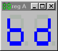
A framework to connect the THRSim11 simulator to external components was
designed and implemented by former student (graduated in January 1997) Alex
van Rooijen. Another student Bart Grootendorst finished up some loose
ends and made this framework ready for distribution. This framework is build
upon Microsoft's COM (Component Object Model) framework and is called the
THRSim11 CDK (Component Development
Kit). This framework will make it possible for you to develop
components you can connect to the THRSim11. These components will be
registered in the windows registry. After installation (with automatic
registration) the THRSim11 simulator will recognize the new component and
this component can be connected to the simulated 68HC11 chip. You need THRSim11
version 3.20 or higher to use these components.
|
|
 |
-
Traffic lights.
Developed by Bart Grootendorst. You can connect this traffic light to three
output pins of the THRSim11. Each light can be switched on or off individually.
You can also use more traffic lights at ones to simulate a crossing.
|
 |
-
Loggers. (Version 2.32 some minor bugs were corrected since
version 2.3)
Developed by Patrick Koorevaar. With these loggers you can log all changes
of a pin, a register or a memory location. The time of each change and the
new value are logged in a listwindow. You can write the contents of the
listwindow to a file for off-line analyses. These loggers are ideal for analysing
timing problems.
|
 |
-
Inserters. (Version 1.33 some minor bugs were corrected
since version 1.3)
Also developed by Patrick Koorevaar. You can use these inserters to insert
data into a pin, a register or a memory location. The data can be generated
manually or come from a comma separated list file (e.g. recorded by a logger).
|
 |
-
Logic (And, Nand, Or, Nor, Exor, and Inverter).
Developed by Harry Broeders. This component has two input pins and one output
pin. You can select between the following logic functions: And, Nand, Or,
Nor, Exor, or Inverter.
|
 |
-
Connection.
Developed by Harry Broeders. This very simple component just sends to pin1
whatever you send to pin2 and vice-versa. This component is ideal for testing
purposes.
|
 |
-
Connection with
switch.
Developed by Harry Broeders. The switch shown in the diagram can be closed
to connect 2 pins. The state of the switch and the signal levels are also
shown in the window title. In the screenshot shown here the logical level
at pin 1 is 0 and the logical level at pin 2 is 1 and the switch is open.
|
 |
-
Resistance measurement circuit.
Developed by Patrick Koorevaar. With this component you can use a wheatstone
bridge to determine the (unknown) value of a resistance.
|
 |
-
Analog Signal and Square Wave Generator generator. (Version
1.25 some bugs were corrected since version 1.2)
Developed by Patrick Koorevaar and partly implemented by Harry Broeders.
With the square wave generator component you can generate a square wave
on a digital input pin. You can adjust the period time and duty cycle. With
the analog signal generator you can generate a sine, saw-tooth, or triangle
wave on an analog input pin. You can adjust the frequency, amplitude and
offset.
|
 |
-
Analog and Bit Oscilloscope. (Version 1.0)
Developed by Patrick Koorevaar and partly implemented by Harry Broeders.
With this relatively simple oscilloscope you can visualize analog and digital
signals. You can adjust the time/dev and volts/dev using the pop-up menu
(right click your mouse).
|
 |
-
OCx. You need THRSim11
3.30 or higher to use this!
Developed by Marco van der Holst using Visual C++ 6.0. This component displays
all registers and flags that are relevant when you use the Output Compare
mode of the timer. You can choose between OC1 through OC5.
|
 |
-
Keypad. You need THRSim11
3.30 or higher to use this!
Developed by Harry Broeders using Borland C++ Builder 5.0. This is a simple
telephone keypad. The keys are connected in a matrix configuration so you
have to write a scan program to read the keys.
|
 |
-
Beerbasement. You
need THRSim11 3.30 or higher to use this!
Developed by Paul Zandbergen using Borland C++ Builder 5.0. This is a simulaton
of a basement which can be used to keep your beer cool!
|
 |
-
Null modem.
Developed by Harry Broeders. This very simple component just sends to Rx
whatever you send to Tx. This component is ideal for testing the SCI (Serial
port).
|
 |
-
Elevator.
Developed by Wilbert Bilderbeek and Harry Broeders. This component simulates
a building with 4 floors and 3 elevators.
|
 |
![]() )
Please note: This package is
included in the install for THRSim11 version 5.xx.
)
Please note: This package is
included in the install for THRSim11 version 5.xx.


